

|
Building a Home Slot Car Track
Text by Larry Geddes – Photos by James J. Van Scoter
Scroll down for the pictures
If you’ve finally made the decision to rout your own track, but you’re a little intimidated about getting in over your head, don’t worry. It’s actually not that difficult once you get started. Although we have some prior woodworking experience (which helps), this is our first track, & we’re pretty pleased (& surprised) with the way it’s turned out so far. The track plan is pretty simple, which helps make it easier to build. The simple design should also make it a fairly fast track, which was one of our goals (We admit to being speed-crazed morons at heart). The bank & the bridge both add some complexity, so if you prefer a flat layout, it should be even easier for you than it was for us. So, for your own track building edification, here is a brief description of HOW WE DID IT. We hope that you enjoy it & can use it to develop some ideas for your own layout.
The first thing you’ll want to do is to accurately measure the space you have available for the track, & then make a large-scale drawing of the space & the track plan. Our space is 11’9” x 19’3”. The larger the drawing, the more accurate you can make it. Use a scale of 1/10 or 1/8. Remember those drawing lessons from high-school geometry, where you had to draw a line perpendicular to another line using a compass & straightedge? Those techniques will come in handy here (so I hope you paid attention). You will also need a decent plastic protractor, a mechanical pencil with 0.5 mm lead, a good eraser, like a Pink Pearl, & a few sheets of 20” x 30” poster board.
You can also use a drawing program on your computer, such as Microsoft PowerPoint, but the final drawing should be on paper. Besides verifying that the track will indeed fit into the space, the drawing will show the exact length of all straights & the degrees of arc (curve angle) of all curves. This information is necessary when cutting out all the pieces. If the design you want won’t fit into the available space, you’ll just have to doodle around with it until you come up with a variation that will fit. It’s better to find this out now than later!
It is at this planning stage that you want to finalize the lane spacing (ours is 4”) & the minimum curve radius (ours is 18”). This will dictate what scale can be run on the track, & how the track will drive. Also give some thought to how much aisle space you need around the outside for drivers & turn marshals. Your plan should also include a bill of materials & a work schedule. Our situation dictated buying material & working on construction over a period of many weekends.
The actual track building begins with a suitable table on which to mount the roadway. We built a platform of ¾” plywood on 2×4 stringers, supported with sawhorse-like legsets. The plywood deck overhangs the 2×4 framing about 10”-12” all around, so that the deck can be contour-cut to match the roadway without cutting into the framing. This is optional – if you like, the table can simply have square corners. This provides some space for scenery, but will make it harder to reach across the track, & harder to run around the track (like between heats). We initially built the table 30” high, which would be fine for a flat track, but later lowered it to 20” to allow for the height of the risers necessary for the bridge & bank, & also to give better visibility. It may seem like a waste of plywood, but a continuous deck such as this allows you to attach risers anywhere on the surface, & also gives you a reference plane from which to take height measurements. Our main table is 6’ x 17’6”, with a 4’ x 7’ wing table on one side.
The roadway is made from ½” MDF (medium-density fiberboard). Our local lumberyards did not carry this thickness & had to order it for us. It is the ideal material for routed tracks. It is easy to machine, has a very smooth surface, & is surprisingly quite flexible. Cutting the straights is of course no problem, just clamp down a straightedge to guide your saw, but the curves are a little more involved. The outer edge must be smooth & truly circular, & the curve angle must be very specific. There are 3 special jigs that we made to produce the curves, one to lay out the inner & outer curve edges with a pencil, one to rout the outer edge (after rough sawing), & one to guide the saw for the radial end cuts, governing the curve angle. Drill a 5/16” hole in the MDF panel & secure a bolt or threaded rod in the hole with jam nuts to provide a fixed center for all 3 jigs. The final step after all jig work is done is to remove the bolt & saw out the inner edge freehand, just following the layout line. The completed curve blank should resemble a piece of plastic track, only larger. If the desired curve won’t fit on a single sheet of MDF, make 2 curves of half the curve angle & splice them together permanently. We had to do this for the donut section of our track; it is 6 feet in diameter.
The straights are actually half-length, so that the pieces can be spliced together into sub-assemblies, each one consisting of a half-straight, a curve, & another half-straight. These sub-assemblies are then routed separately, then spliced together end-to-end, so that the final joints occur in the middle of the straights. The router jig we used for the first (outer) slot has 2 rollers (These are 1-3/16” OD ball bearings mounted with bolts; you could probably use replacement rollers for patio doors.) that must always follow the outer edge of the curve; it just won’t work against the inner edge. Handling the track in sub-assemblies allows the roller jig to follow outer curve edges only, regardless of whether the curve is left-handed or right-handed. We routed the slot .350” deep. This will accept any guide, even a Cahoza, the deepest we could find.
It should be mentioned here that the spacing between the rollers on the router jig is important, because it will determine how much wider the outside gutters are in the curves than they are in the straights. This gutter-widening effect happens automatically, & is a function of the jig’s geometry & the curve blank radius. The further apart the rollers, or the smaller the blank, the wider the gutters become in the curves. Our outside gutters go from 4” on the straights to 6” in the curves, & with a curve blank of 36” radius, the jig required a roller spacing of 23.8” to achieve this. All our curve blanks were about the same radius, so this roller spacing was used on all curves. If your curve blanks vary in radius, but you’d like to maintain the same gutter width on all curves, you must build your roller jig with several different mounting holes for the rollers, so that you can select the appropriate roller spacing for the curve you’re working on.
Since the outer gutters get wider in the curves, the inner gutters naturally must get narrower. Our roadway width is 20” on the straights, giving us 4” gutters on both sides. In the curves, the outer gutter grows to 6”, as mentioned, with the result that the inner gutter has to shrink to only 2”. In order to end up with a decent inner gutter, we added 1” to the width of the roadway of all curves, making it 21”, & giving us a 3” inner gutter, which we feel is adequate. The 1” step where the straights meet the curves were blended in later with small triangles of MDF.
Once the first slot has been routed in all sub-assemblies with the roller jig, the router is removed from this jig & set up in the other slot jig, this one having 2 guide pins that guide the jig using the first slot. This pin jig is used to rout all the remaining slots, with the pins following the previous slot in succession. The pins in this jig are slightly under 1/8” in diameter, about .120”, so they slide freely in the slot, but without too much play. Unlike the rollers in the first jig, they are spaced only 4” apart, because no additional widening effect was desired on the inner 3 lanes. The slot-routing jigs require a certain amount of extra material at the free ends of the straights, since the slot can’t be routed all the way to the end (Both rollers must be against the edge at the start & finish). Each half-straight is therefore initially cut with 24” of extra “waste” material added to its length. A starter hole is drilled in which to start the router bit for each slot. After all routing, this waste material is simply cut off so that a straight of half-length is left. The slot spacing is maintained with the pin jig in all subassemblies, so the slots WILL line up when the sub-assemblies are joined. Trust me!
If you plan on using braid instead of copper tape, the braid recesses must be routed after all slots are cut, but before the waste material is sawed off the straights. You will probably have to either contact a track builder to obtain the special cutter required for this, or have a tool grinding or machine shop make one for you. The braid should end up slightly below the track surface, about .010” – .015”.
An interesting side-effect of using this approach to slot routing (elliptical routing) is that the transition from straight to curve is not tangential, as it is in plastic track, or track routed with straightedge & trammel. It is actually a spiral, with the straight turning into the curve in a constantly decreasing radius, until the final curve radius is reached. This means that the cars will not be subjected to a sudden change in direction, but will undergo a more gradual change when entering & exiting the curve. We believe this feature will make the track very fast & smooth driving.
The bank was actually quite easy to make. The basic principle is that you start with a curve of smaller angle than on your track plan, then just push the two attached straights toward each other until the desired curve angle is reached. The bank will pop up by itself. In our case, we wanted the bank to have a curve angle of 200 degrees after bending, according to our drawing. We cut the curve blank to 190 degrees & pushed the straights together the final 10 degrees to obtain the desired 200. We also made the blank 3” larger in diameter than that called for on the drawing, to allow for shrinkage during bending. We arrived at the before-bending figures by experimenting with a 180-degree curve-&-straight subassembly that was to be used elsewhere in the track, taking before-&-after-bending measurements to see what to expect. The straights leading to the bank should be elevated several inches above the table, because the inner edge of the bank will want to dip down below the level of the straights. If it pushes down against the table, it can cause some deformation of the straights, which could result in “launching ramps.”
Once you reach this point, you’ve pretty much got it made. All that remains is to splice the sub-assemblies together & mount the roadway to the table on risers. All our splices are ¾” birch plywood, 3” wide, spanning the width of the roadway, & secured with countersunk #8 flat head wood screws, ten per joint. The risers are mostly made from leftover scraps of MDF, with 1×2 cleats top & bottom to attach to the roadway & table. They are made in two parts, so that a little adjustment is possible, similar to the supports found under a typical commercial track. Short risers are ripped from 2x4s & placed on edge. A certain amount of fiddling will be required to determine the dimensions of the risers & the final roadway position. We used temporary supports to prop up the roadway (paint cans, blocks of wood, etc.) that could be moved around & changed easily during this stage. When the last riser is finally in place, the hardest part of track building is over. All the rest is fairly cut-&-dried.
Before any painting is done, drill holes next to the slots for electrical taps to be added later. We will be using .0015 x 5/16” copper tape & tapping it with #6 – 32 flat head brass machine screws let into countersinks at each hole. We are using 3 tap locations spaced equally around the 55-foot lap, one set of taps every 220”, so that there will never be more than 110” of tape between the car & the track power.
Frankly, we are not too familiar with how braid is terminated at the tap locations. We didn’t investigate this because we didn’t plan on using it. We would recommend contacting a track builder to find out the specifics, & what method would be best for a home track. We felt that tape would be adequate for a home track that will not see the amount of use (or abuse) of a commercial track.
Our next installment should wrap up the rest of the project, with paint, copper tape, & wiring. We hope we have inspired you to dust off your imagination, fire up your power tools, & give it a try. We’d also like to thank Paul Kassens, the Old Weird One himself, for letting us share this with you, so – – – Thanks, Paul!
(OWH Webmeister note: Thank you Larry & Jeff!!! 🙂
Larry Geddes & James J. (Jeff) Van Scoter
email: geddes@erie.net – vito98@erie.net
(Note – Click on images for larger view – use browser’s “back” button to return)
PHOTOS
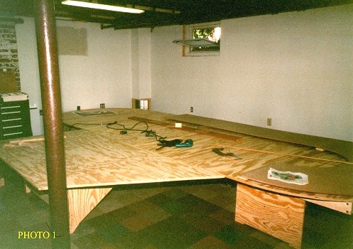 |
1) The basic bare table. Has a ¾” plywood top, height is about 20” above the floor. The lead-on & part of the main straight can be seen at the right. |
| 2) The bank feasibility study in progress. This is actually the section of track seen in photo 1, turned around & being used as a guinea pig. | 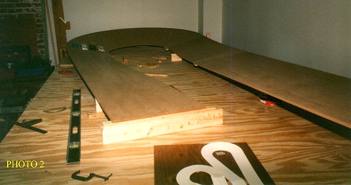 |
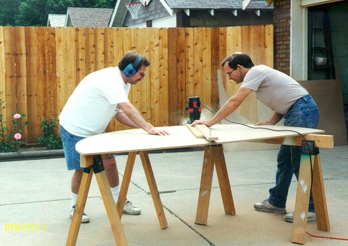 |
3) The proprietors J&L at work, using a router trammel to finish-contour the OD of a curve. |
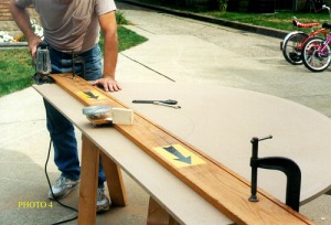
| 4) The included angle of the curve being cut with a special jig. The protractor is set to “zero” & the first cut made… |  |
 |
5) …Then the jig is rotated the desired angle & the second end is cut. This is a 140-degree curve for the dead-man. |
| 6) The finished curve, after cutting out the center. |  |
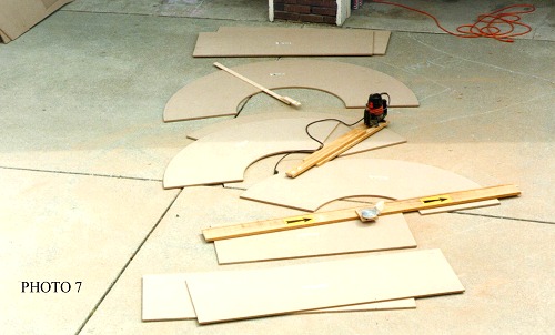 |
7) Most of the pieces for our track, & the jigs that made them. The three curves, from the top, are the bank, the 2-piece donut, & the dead-man. (The lead-on is not shown) The jigs are, top down, a marking gauge for drawing the OD & ID of the curves, the router trammel for finishing the OD of the curves, & the angle-cutting jig. |
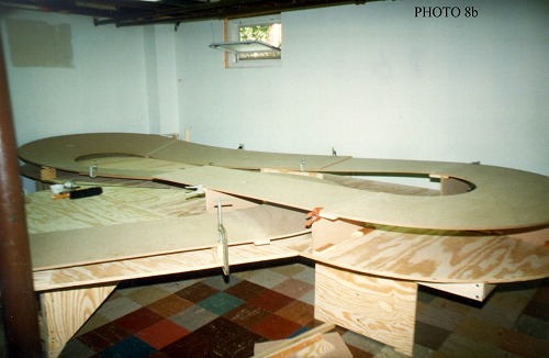
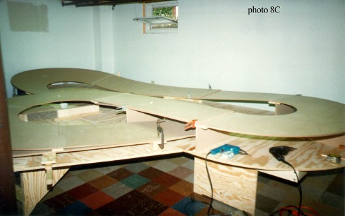
| 8) a), b) & c) Track pieces being test-fitted prior to routing. Excess material on the straights is simply overlapped at this point. | 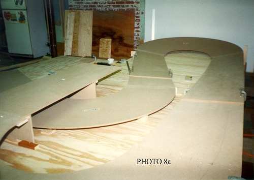 |
 |
 |
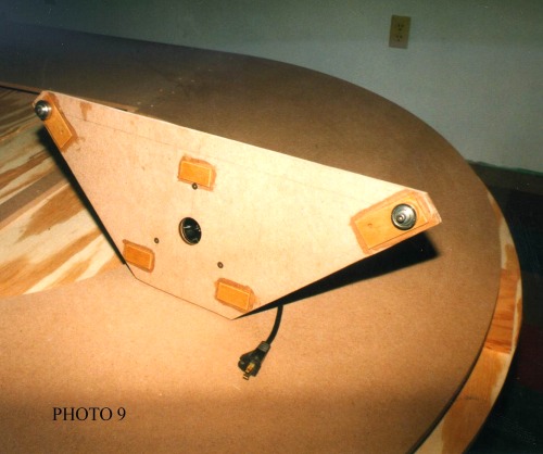 |
9) Bottom view of the roller jig used to rout the first slot. Note the ball-bearing rollers that ride on the edge of the track. |
| 10) Top view of the roller jig. Cutter is raised. | 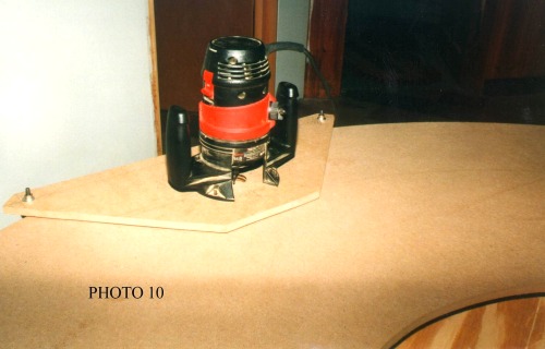 |
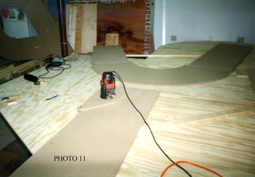 |
11) The roller jig ready to cut the first slot. Cutter is inserted in a starter hole. |
| 12) The pin jig, cutting the last slot. This jig has two 1/8-inch pins that ride in the previously routed slot, maintaining the lane spacing. |  |
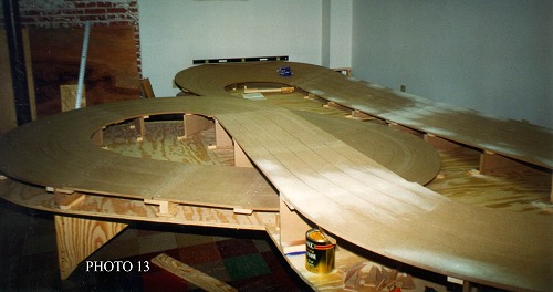 |
13) Track is now completely routed & spliced together. Most of the risers are in place, & screw holes & joints are being filled. |
| 14) The view from the bank end. The hole in the table just before the dead-man is for wiring access to the taps. | 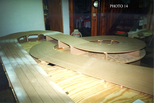 |
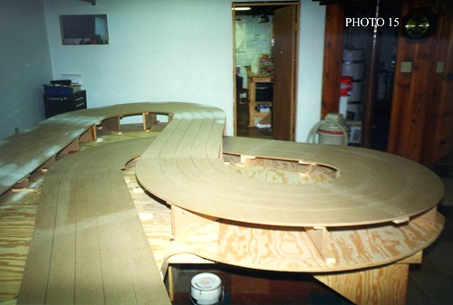 |
15) View of the donut. Here the gutter transitions can be clearly seen. |
| 16) A low view down the main straight. | 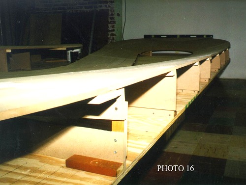 |
(Note – Click on images for larger view – use browser’s “back” button to return)
CLICK HERE FOR THE STORY


Comments are closed.