

|
Formula One/Indy Chassis Project
By Larry Shephard 07-04-00
Introduction
I realized the other day that I had never built a 1/32nd scale open wheel formula car. I then decided I needed to do so. I obtained a couple of Betta 1/32nd scale formula bodies from Jon at Rad Trax in Las Vegas and set out to build a state of the art, (for me), chassis to use with them. It would be a brass/wire scratch built frame and I decided to write up the “how to” on one. The following is an outline of the basic process used to produce what turns out to be a very nice running and handling car for these formula bodies.
Parts I used you will need
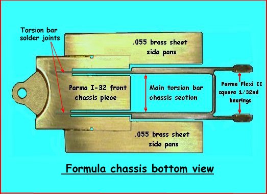
I used a Parma I-32 brass chassis nose piece left over from a proxy car chassis that had used the rear end for the motor/axle mounts. It was cut off just in front of the I-32 chassis plate upstop. The rear bearings are from a Parma Flexi II chassis that uses the square shape bearings that allow a four position wheelbase and ride height adjustment. I like these as they are very easy to align and set up for a scratch chassis. I used the 3/32nd inch axle size though they also come in 1/8 inch axle size. The other commercial part, besides the guide, is the Sonic all brass crown gear in 64 pitch. They come in a nice small diameter and in 31-35 tooth selection. They mesh up with most steel pinions very well. The small diameter eliminates most chassis clearance problems. The following picture will show most components needed for construction.

The most difficult part to fabricate is the U shaped .055 dia music wire main frame rails. They need to be bent to allow 5/8inch (.625) between the parallel rails. They need to be approximately 3 & 7/16 (3.437) inches long depending on the body you use. This width will allow the Pla-Fit Cheetah/Fox type motor to rest on the bench flush between the rails.
The next piece to make is the front brass frame part. This is the I-32 part shown here. You could make it out of sheet brass and add the guide shoe pivot of steel or brass and solder it on top just as well. I used the I-32 as I had it and it made things a little easier for me. The brass piece must be slotted to allow the rails to fit down flush with the bench and allow room to solder them solid to the brass. I left the slot 3/8 (.375) inch short of the front of the brass piece. The slot at the front must be a loose fit for the .055 dia. rails. This allows room for the solder to flow in and around the rails. This must be a good tight joint. Use plenty of heat and let the solder flow. Make sure it is all very clean with bright metal showing. Use a good flux. The rear of the slots must be close to 1/8 (.125) inch wide so as not to interfere with the movement of the rails later. I only solder the front 3/8 (.375) inch of the rails into the brass piece. You can adjust this later with a Dremel and a cut off disk if you want more chassis flex or solder more of the rail if you want less flex.
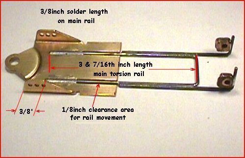
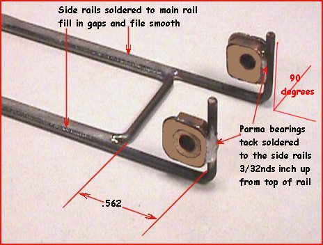
The above picture shows the rail placement. It also shows the side rails soldered to the main rails. These side rails are .055 dia. music wire 2 1/16″ (2.062) inches long to the right angle bend. This bend up should be about 1/2″ (.500) inch long. This allows plenty of room to position the rear bearings which are tack soldered to the rails before soldering the side rails to the main rails. I tack them in place with a 3/32nd axle spacer up from the side rail top to locate them, as per following picture.

Once both are soldered in place, place an axle in the bearings. Position the rails in place next to the main rails almost touching the brass front frame. Lightly tack solder them in place to allow some positioning if necessary. Align the axle perpendicular to the frame by drawing lines on the bench that are perpendicular or use a frame jig to align. Also make sure the side rails are bent up at 90 degrees. When soldering to the main rails, the axle should help keep the bearings and uprights to also be 90 degees to the side of the frame. See next picture.
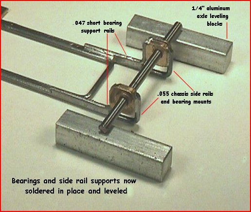
Next we need two axle alignment blocks. I made mine out of 1/4″ (.250) inch aluminum bar I found at the hardware store. You can use any 1/4 inch block as long as it is hard and true. The bottom of the 3/32nd axle must rest flat on top of these blocks. With the axle in the bearings see how much adjustment up or down you must make to get it flush and flat. To adjust, just heat the tacked solder joint of the bearing to the rail, with a soldering iron till the solder melts. Then push down on the axle, one side at a time, till the axle sits flat on the alignment block. Do a little at a time to each side till they both are down and flush. The axle should now move back and forth in the bearing easily and it should rotate VERY freely. This makes a big difference in how the car will run and handle. So spend the time necessary getting this right.
Solder the side rails tight to the main rails when fore and aft alignment is set. Fill in the solder hollows and file the rails smooth. This makes a good solid joint and also looks nice. Next we want to take the other short .047 dia. L shaped pieces and solder them to the front of the bearings and on top of the .055 side rails. These provide support and stiffen the rear of the frame. Again use a good flux on clean joint surfaces, and, after tacking in place, fill in the gaps and file smooth to make a good strong joint. Now cut off the ends of the frame rails sticking above the bearings to make a nice smooth clean looking structure around the bearing.
The side pans are next. They are made of .055 or .060 sheet brass if you have that instead. I made them 2 1/2″ (2.500) inches long. They are notched to fit to the front frame piece. My notch was 1 3/16″ (1.187) inches long by 3/16″ (.187) inches wide. Adjust the widths to suit the body you use. When fitted they should be close to the width of your body, mine was just under 2″ 2.00 inches wide. Solder them to the front of the brass frame piece when flat against the bench keep the bottom surfaces as flat and level as you can. Also make sure the side pans do not rub against the main rails or the side rails to allow maximum movement.
The above view shows the near complete chassis and shows the clearance areas around the chassis main rails to allow the torsion effect. This allows an up and down movement, a slight side to side travel and some twisting or torsion effect to the whole chassis. I have not added a down stop for the pans and they can go down as well as up. They have not dragged anywhere yet but you may need to add some on your track. Some short lengths of music wire soldered near the rear of the pans on top would stop any down ward travel and would be sufficient. If you use some larger OD brass tubing soldered on the rail that the wire would ride inside of, you could also limit the up travel some if you feel it is too much. This will also restrict the twist motion.
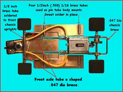
The above view shows the front axle tube 1/8 inch dia. soldered in place. To do this, mount the guide shoe with brushes in place and set the center piece chassis ride height for 1/16″ (.062) inch chassis clearance in front. Place the axle in the axle tubing, spaced to allow the clearance you need for the front wheels used. Mount the wheels and tires on the axle in the tubing and place in position so it touches the front of the I-32 front axle uprights. When it touches evenly, tack solder it in place. If you want the front tires off the ground a bit, add some shim stock under the tires before tacking. When you have it where you want it and the wheel base is right, put in a U shaped .047 dia music wire brace that touches the axle tube for most of its length within the I-32 uprights. Solder it there firmly and then apply solder to the legs that should hang down a bit inside the I-32 uprights.
At the rear of the chassis I added a .047 dia. U shaped piece of music wire that fits between the two side rails and is soldered in place. This stiffens the rear end and prevents the bearings from moving out of alignment under hard cornering or in a crash. A little bullet proofing never hurts. It only extends back about 1/2 (.500) inch to the rear. It also acts as a bit of a nerf bar in rear end collisions.
The motor is soldered at the bottom rear to the back of the U shaped main chassis rail. Solder while the whole assembly is flat on the bench, you do not want the motor hanging down below the frame anywhere. At the front of the motor to prevent any chance of it coming loose I made another small U shaped piece of .047 dia music and solder it to the main rails on both sides while almost touching the rear of the motor case. Then when in place solder the cross piece to the front of the motor carefully so that solder does not hang down below the frame. If it does file or grind it flush. When you have the gear mesh the way you want, make a brass bushing or use a spacer washer thick enough that fits over the axle and is just the right lenght (trial and Error) to fit snug between the gear and the near bearing. This prevents the gear from easily slipping back away from the pinion.
If you used just flat sheet as a front chassis piece you will need to add some uprights to support the front axle tube. I did not make the front wheels independent at this time but will at a later time. It handles very well right now but on a tighter track I will want to make them independent. There is plenty of room to add weight if you feel it is necessary. It depends on your track conditions. All you have to do now is add the lead wires and mount the body so you can see the pin holes through the clear body and then paint it and go racing.
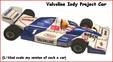
Another version I have just finished looks like this. Neither paint job is of a real car, only as they could have looked.
By Larry Shephard 07-04-00
Related posts:
 Proxy Race II Prototype Car Building
 A Cheetah on Steroids
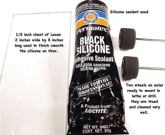 Silongies, You Ask? Making silicone coated sponge tires!
 Building the J & L Raceway ~ Part 2 ~
 Racing Without Agony
 Ninco Mercedes Upgrade Project
 The Wheel of Fortuneless
 The First Slot Car Big Mag “How To” – by Josh Bauer
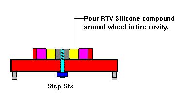 Silicone Tire Casting 101
 Building the J & L Raceway ~ Part 1 ~